
Reduces the abrupt change in stiffness between lighter drill pipe and heavy BHA components.
DRILL STRING PRODUCTS
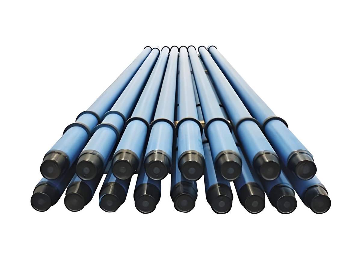
Heavy Weight Drill Pipe
Transition components designed to add weight and stiffness between drill pipe and bottom-hole assemblies.
StandardAPI 7-1 · API 7-2 connection references
Size / supply rangeOD, ID, length and upset geometry confirmed against the BHA design · Integral and welded configurations
Grades / materialsAISI 4145H Modified typical integral material · Pipe-body and tool-joint materials for welded designs
Connections / optionsAPI rotary-shouldered connections · Selected proprietary connections
DRILL-STRING TRANSITION COMPONENT
Added weight and stiffness between drill pipe and drill collars.
Heavy Weight Drill Pipe (HWDP) is an intermediate-weight drill-stem component used to create a more gradual stiffness transition between conventional drill pipe and the bottom-hole assembly. In directional wells it can add weight on bit, reduce abrupt section changes and help manage buckling and fatigue.
OAK’s existing product information covers integral and welded HWDP routes for vertical and directional drilling. OAK PIPE coordinates body construction, center upset, tool joints, connections, hardbanding and inspection around the drill-string design.
Supports axial load, torque, bending and compressive service in the transition zone.
Center upset, wear pads, spirals and hardbanding are configured for the intended well path.
SUPPLY OVERVIEW
Typical HWDP specifications.
OAK’s construction and material statements form the supply basis. Dimensions and connection geometry are finalized for the requested drill-string configuration.
| Product reference | Heavy Weight Drill Pipe manufactured to the agreed API 7-1 / project requirements |
|---|---|
| OAK published constructions | Integral type and welded type |
| OAK integral material statement | AISI 4145H Modified, quenched and tempered / heat treated to the required properties |
| OAK welded construction statement | AISI 4145H tool-joint / end components with 1340-series tube body, subject to final material specification |
| Typical industry size enquiry range | Approximately 2⅞ in through 6⅝ in nominal body size; OAK availability confirmed by construction and connection |
| Nominal length | Commonly around 30–31 ft, with exact length and tolerances defined by the order |
| Connections | API rotary-shouldered or authorized project connection; tool-joint OD, ID and make-up requirements must be stated |
| Body configurations | Standard center upset, spiral / tri-spiral or other project configuration where available |
| Wear protection | Specified hardbanding on tool joints and center section / wear pads where required |
| Marking & protection | Serial traceability, connection protection and export packing matched to handling requirements |
The size envelope is an industry purchasing reference used to structure enquiries; OAK’s confirmed offer governs each size, connection and construction combination.
CONSTRUCTION ROUTES
Integral or welded, selected for the required assembly.
The construction route affects material specification, section transitions, weld-zone control, tool-joint geometry and inspection planning.
| Construction | OAK information basis | Technical review focus |
|---|---|---|
| Integral HWDP | OAK identifies AISI 4145H Modified heat-treated steel for integral construction | Through-section properties, center upset / spirals, bore, connection and full-length NDT |
| Welded HWDP | OAK identifies 4145H end components / tool joints with a 1340-series tube body | Tube-to-end transition, friction-weld route where applicable, weld-zone heat treatment and NDT |
| Special-service HWDP | Available only after material and operating-condition review | Strength, hardness, toughness, H₂S exposure, temperature and qualification tests |
| Drawing-specific HWDP | Configuration developed or matched from approved purchaser data | Critical dimensions, load envelope, interchangeability and inspection hold points |
BODY CONFIGURATIONS
Configure contact, wear and hydraulics along the body.
Industry designs use different center-section geometries. OAK confirms the applicable form and dimensions against the requested size and connection.
STD
Standard HWDPHeavy-wall body with enlarged center upset for wear protection and transition stiffness.
Spiral
Spiral HWDPSpiral profile around the center section can reduce contact area and assist pressure equalization.
Tri-Spiral
Multiple Wear PadsMultiple spiral wear sections provide distributed contact and wear protection where specified.
Integral
One-Piece RouteIntegral construction avoids a tube-to-tool-joint weld and requires full component property control.
DRILLING APPLICATIONS
Placed where drill-string stiffness and weight change.
Quantity and position in the string should come from the drilling and BHA design rather than a fixed rule.
Transition Zone
Installed between drill pipe and drill collars to moderate stiffness change.
Directional Wells
Adds weight and stiffness while supporting buckling control in deviated sections.
Extended-Reach Drilling
Used in modeled string configurations where torque, drag and fatigue govern.
Vertical Drilling
Provides intermediate weight and can replace selected drill-collar length where designed.
Compression Service
Supports planned compressive loading with body and connection stability reviewed.
Sour / Special Service
Requires explicit environment, strength, hardness and qualification requirements.
OPTIONAL FEATURES
Wear and fatigue details belong in the purchase specification.
Hardbanding brand or classification, placement, center-upset geometry, connection treatment and stress-relief features should be specified with measurable acceptance criteria.
Tool-joint hardbandingCenter-upset hardbandingSpiral / wear-pad geometryThread-root cold rollingStress-relief featuresConnection phosphate treatment
MANUFACTURING & QUALITY
Inspect the complete transition component.
The route follows the actual construction, with special attention to heat treatment, section transitions, weld zones and rotary-shouldered connections.
01Specification, construction and drawing review
02Material identity and heat-treatment control
03Body, center upset / spiral and bore machining
04Tool-joint or end manufacture and connection machining
05Weld-zone control where applicable, NDT and dimensions
06Hardbanding, connection inspection, marking and final release
Typical available documents
Material Test Certificate · Chemical and mechanical results · Heat-treatment records · Weld-zone records for welded construction · Full-length / end-area NDT · Dimensional report · Connection inspection · Hardbanding report · Certificate of conformity · Third-party inspection records
HWDP RFQ CHECKLIST
Define the construction, connection and wear system.
A complete enquiry allows the body and tool-joint geometry to be checked as one drill-string component.
Request an HWDP Quote- 01Nominal body size, quantity, overall length and integral / welded preference
- 02Body OD / ID, center-upset or spiral dimensions and required weight
- 03Exact pin and box connection with tool-joint OD and ID
- 04Material / strength, operating loads and special-service environment
- 05Hardbanding system, placement, stress-relief and thread treatment
- 06NDT, dimensional, connection, documentation and packing requirements
PRODUCT & PROCESS VIEWS
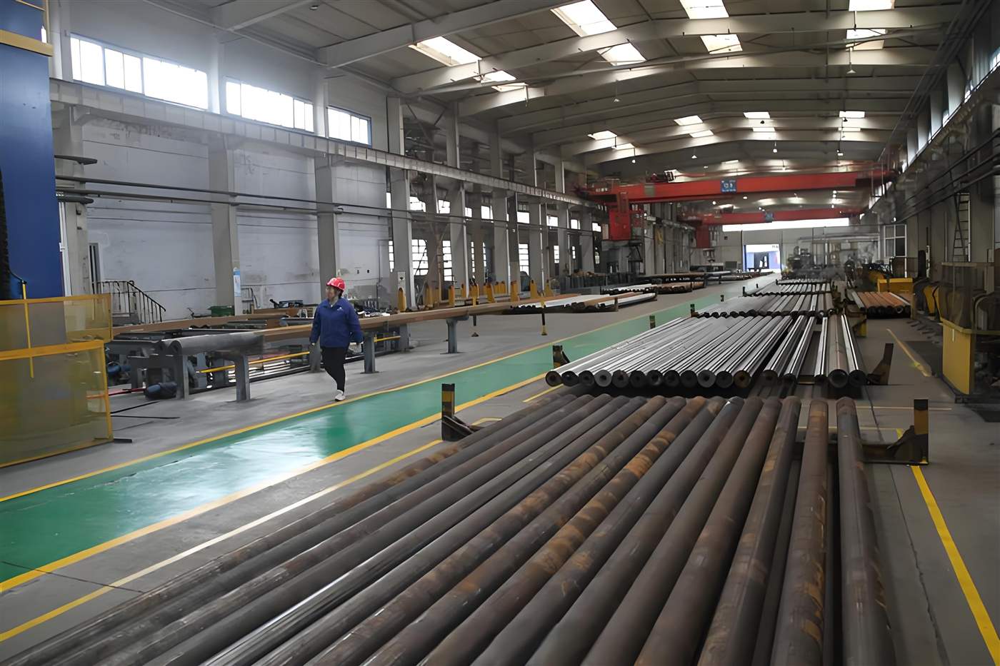
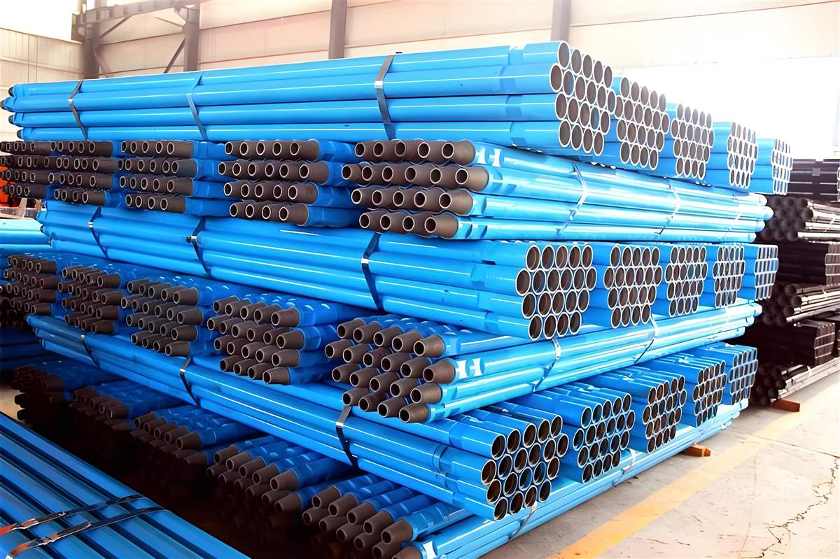
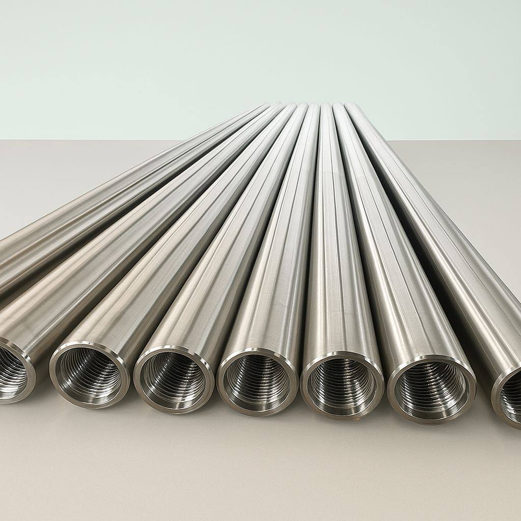
Product views and manufacturing context.
Representative product, production and inventory views support preliminary identification. Final supply details are confirmed against the quotation.
START A CONVERSATION
Have a specification or product list?
Send it to OAK PIPE for technical and commercial review.